

Last time I introduced my EPD project’soverview.Today, I introduce the ED050SC3 Electric
Paper Display.
This screen size is 5 inch and resolution is 800 x 600 dots. The datasheet is here.
This is too old EPD. It manufactured since 2008. But we can still get it as maintenance
parts.
The ED050SC3 has 33pin 0.5mm pitch Flat
Flex Cable (FFC/FPC). It was very important to choose EPD.The recent EPDs needs a special connector. it
is difficult to get or expensive.but we can find the FFC connector easily. For example thelist of searched at Digikey.
The pinout
There are 8pins for power source, 10pins
for control signals and 8pins for data transfer. 7pins are not connection.
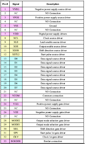
pink is power.yellow is control signals.blue is data.
The power source
The ED050SC3 need many kind voltage power
sources.
VNEG(-15V) and VPOS(+15V) are for source driver. VGG(+22V) and VEE(-20V)
are for gate driver. VDD(+3.3V) and VSS(GND) is for digital logic. There need
power on sequence. VDD -> VNEG,VEE -> VPOS,VGG. The delay needs longer 100us.
VCOM(-2V) is for common connection. It affected
to displayed image. When the EPD is active ( turn on the device), The supplied voltage is -2V(from -1V to -2.5V). I didn’t find the affect to displayed
image difference from -1V to -2.5V. This power source’s impedance should be low. If it is
high ( about >100ohm ), displayed image is low contrast. And if the EPD is turn
off ( cut the power source ), VCOM pin should be high impedance. Otherwise the
screen’s color is changed to gray little by little after the power cut off.
BORDER(-15V, +15V or no connection) is set
the border color around the screen. The border color is white, if it ties to
-15V. Black is +15V. It is no connection if you never mind to color.
The control signals
There are two drivers into EPD. They are the
source driver and the gate driver. The source driver controls 800 dots data for
horizontal direction. The gate driver controls 600 lines data for vertical direction.
These control signals sequence were not written on the datasheet. So I have
hacked the e-book reader by logic analyzer. The detail is here( sorry written in Japanese. I may tartrate it to English later.
)
The source driver
You need control XCL, XLE, XOE and XSTL2.
XCL take the data signals(8bit) in source driver when
the rising edge.
XLE set high when the one line data (800 dots)
are finished to transfer.
XOE set high basically for data transfer period.
XSHR is tied high. It was not working when it
was tied to low.
XSTL2 set low before start to transfer the
data.
The gate driver
You need control the MODE(1,2), SPV, CKV
pin.
MODE1 and MODE2 are tied together. MODE is set
high first of all control signals.
XRL is tied high. It was not working when it
was tied to low.
SPV is set low before start to transfer the
first line data.
CKV is set high to change next line.
These control signals are complicated in
actuality wave forms. Please see this also.
The data signals
It is 8bit data width. It can transfer 4 dots
data once. the one pixel is consisted of two bits. 1 0 is changing to
white. 0 1 is black. 0 0 is no changing. 1 1 is also no changing but may be
damaged to EPD.
ED050SC3(LF) and ED050SC3(LF) H1
There are two type models the Non H1 and H1.
It doesn’t write on the datasheet difference about it. The function
was the same when it connect
to e-book. But if it was connected to microcontroller and the data
transfer speed is
slow, the displayed image was different.Please see a follow picture.

The Non H1 is left and H1 is right. It took two seconds to transfer data. The H1
model had many black lines like a ghost. The Non H1 model is better choice for us with the microcontroller.
Next time I will share about the ESP8266 block.
Thanks reading.
![]() Contents of the EPD project
Contents of the EPD project
- The project outline
- The ED050SC3 EPD ( You are here )
- The ESP8266( ESP-WROOM-02)
- The Power block
- The 16bit shift register
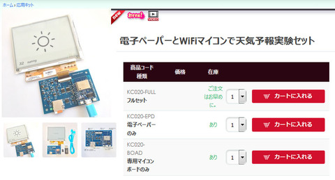
![]() You can buy the EPD experiment kit at our shop.
You can buy the EPD experiment kit at our shop.![]()


コメント
Thank you for reading! I will share the details other blocks of my EPD project to try it anyone.
Thank you.
Hello from India 🙂
Thank you for sharing your progress on this, I will definitely try this project when I have free time. Very nice blog website too!