
Hi. Today I explain about the esp8266
module for my project. The esp8266 is very famous cheap microcontroller has the
Wi-Fi function. There are any types of module. ESP12 is popular module in the
world.
But I have chosen ESP-WROOM-02 because it needs to pass the TELEC certification
to use in japan.

Esp8266 module needs power converter and USB-serial
converter when it run and writes the program. The ESP-WROOM-02 Developer Board
is easy way to develop because it has these functions.
The NodeMCU is popular in
the world. May be the functions are same.
The added circuits

The reset
I added external circuits for the reset on ESP-WROOM-02
Developer Board. The register and capacitor tied to EN pin and the capacitor tied
to RESET pin for power on reset. The RESET pin has a pull-up register on the developer
board yet. So it was added only capacitor at the RESET pin. The IO16 tied to RESET
pin throw the register (470 ohm). It needs to wake it up from the sleep.
The GPIOs
Esp8266 has a few GPIO pins. The EPD needs
many pins for control and data transfer. So I added shift register for extend
Output pins. I explain the details later.
The voltage regulator

The ESP-WROOM-02 Developer Board has a
voltage regulator to convert from the USB 5V to 3.3V for ESP-WROOM-02 module. The
esp8266 needs large power consumption often. This power ability is not powerful
so much to supply for other devices (shift register and SD card). And the USB
5V voltage is dropped down lower 4V throw the USB cable and when the esp8266
is running. The voltage regulator was required the low dropout (LDO) voltage
regulator.
Next I will share the Power block.
Thanks reading.
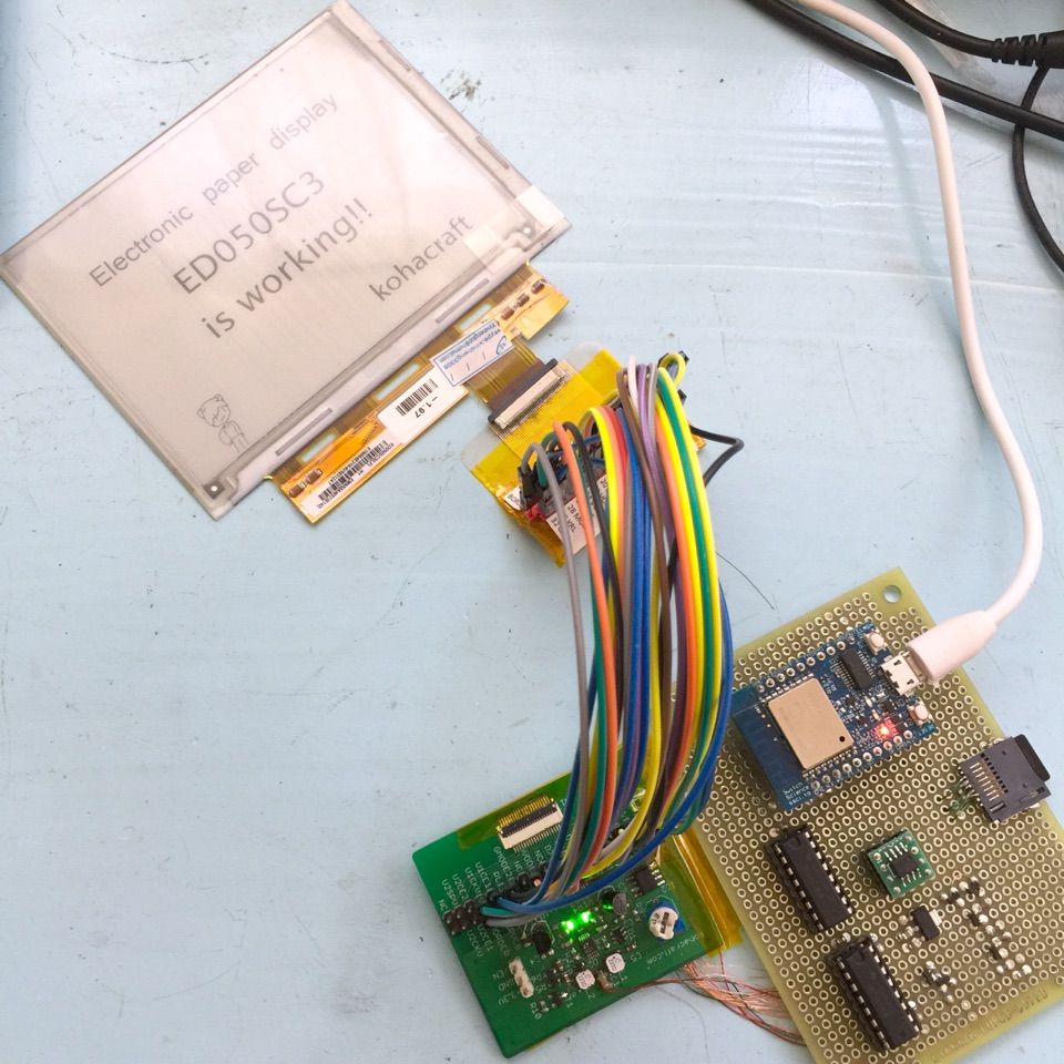
![]() Contents of the EPD project
Contents of the EPD project
- The project outline
- The ED050SC3 EPD
- The ESP8266( ESP-WROOM-02) ( You are here )
- The Power block
- The 16bit shift register
- The SD card and serial RAM
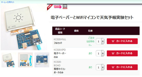
![]() You can buy the EPD experiment kit at our shop.
You can buy the EPD experiment kit at our shop.![]()


コメント