

Hi.
Today I would share the DCDC power
converter block of the EPD project. ED050SC3 heeds many voltages power sources
+22V, +15V, -20V, -15V, +3.3V and -2V. I am assuming that the power source of this
system is +5V by USB. These voltages are converted from +5V.
The top and following figures are shown the block
diagram and circuit of this block.

DCDC convertor
The +22V positive and -20V negative voltages
are converted from +5V by the DCDC converter. The DCDC converter IC is LT1945. The datasheet is here. It is Dual
Micro power DC/DC Converter with Positive and Negative Outputs. It is very
useful to convert to the dual pole voltage. And the circuit makes simply. The feedback
resistors and inductor value were calculated by the formulas on the datasheet.
And it has the Shutdown Pin each pole
converters. They can use for power on sequence the EPD. The power on sequence is
VDD -> Negative voltage -> Positive Voltage. The resistor and capacitor
tied to shutdown pin for it makes the delay as the CR timer. The resistance at the
positive shutdown pin is higher than the negative one. I choose 100k ohm and
10k ohm. The delays ware 1.9ms and 1.2ms at connected the EPD as the load. And the diode is added for the
shutdown quickly when power cut off.
Voltage regulators
The +15V and -15V are converted by voltage regulator.
Because these regulators are easily obtainable as 78L15 and 79L15.
The +3.3V is converted by low drop output (LDO)
voltage regulator.Because the USB bus power is dropped around
4V when running the ESP8266.The SPX3819 is LDO voltage regulator. The datasheet is here. The drop voltage is variable
by the output current. The EPD logic power current is 4mA max. The drop voltage
is less than 50mA. If you cannot get it you must choice device any types of LDO
voltage regulators.
The special power supply for VCOM
-2V for VCOM power supply is special
circuit. Because it was required two functions.
- It needs sink and source current
(push pull current) and continuous voltage power supply when the power on. - It
needs high impedance output when the power cut off.
The following figure is shown the circuit for VCOM.
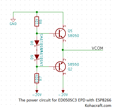
It looks like a Class AB Amplifier. When the power on, the output voltage
is generated by resistor division with resistors 100k ohm and 10komh. The output
voltage was -1.8V. When the power cut off, the two transistors are turned off. So
the output is high impedance when the power cut off.
Next I will share other block.
Thanks reading.
![]() Contents of the EPD project
Contents of the EPD project
- The project outline
- The ED050SC3 EPD
- The ESP8266( ESP-WROOM-02)
- The Power block ( you are here )
- The 16bit shift register
- The SD card and serial RAM
![]() You can buy the EPD experiment kit at our shop.
You can buy the EPD experiment kit at our shop.![]()


コメント