
Hi. Today I would introduce the 16bit shift
register of the EPD project. The function of shift register is converting from a
serial data to parallel data. At least 14 pins (6 pins to control and 8 pins
data transfer) are needed to control ED050SC3 EPD. I want to control it by
ESP8266 microcontroller. It has a few I/O pins. So it needs to extend the output
pins. In such case the shift register has been used to use.
74HC595 shift register IC
74HC595 is most popular shift register IC. Thedatasheet (Texas Instruments) is here. It can convert from 8bit serial data to
8bit parallel data. 74HC595 has two parts of functions.
The first part is the data conversion from
serial to parallel. The serial data (input SER pin) is taken into shift register
when the clock (SRCLK pin) rises. You need eight clocks to set 8 bit data into
the shift register.
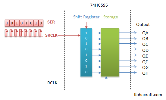
The second part is data storage. It is
keeping the states of output pins while the serial data is transferring. The states
of output pins are changed when latch pin (RCLK pin) rises after finish transferring
data.

74HC595 is able to output 8bit parallel
data by only three pins (SER , SRCLK , RCLK) are controlled.
Also it can add output pins to connect any
74HC595s each other. The /QH pin of first 74HC595 connect to the SER pin of
second one. If you need 16bit output pins, you use two 74HC595. If you need
24bit, you use three.

The following circuit was designed 16bit
shift register by the two 74HC595 for EPD project. It is for controlling EPD by the ESP8266. SER
and SRCLK are connected to SPI of ESP8266. RCLK was connected to IO2 of
ESP8266.
The shift register of 74HC595 had a clear
pin (SRCLR pin). It was connected The RC timer circuit as the power on reset.

But this circuit had problem. The random
pattern was displayed EPD for a few second when the power on. The cause of that…
74HC595’s output pins were High when the power
is on
In most cases, the output pins of 74HC595 were
High when the power was on. Even though there was the power on reset circuit
with the shift register. Because the clear pin (SRCLR pin) can clear only the shift
register (first part of functions). It cannot clear the storage (second part of
functions).

If I want clear all output pins, I must transfer the zero data and
then latch pin rises. Unfortunately ESP8266 needs a few second for internal initialize
(boot) when the power on. For the while cannot control the output pins and cannot
clear the sift register output. So the output pins were high a few second.

The random data from IO2
When the ESP8266 power is on, it needs internal
initialize (boot) time a few second. In the meanwhile the random data is out
from IO2. I don’t know the reason why it. IO2 was connected to latch pin on
74HC595 on my circuit. So the unknown data were latched any times while the
internal initialize.
Solution
I was through 47HC595 away and I use
74HC594 instead. 74HC594 is similar to 74HC595. The different is it has the clear
pin (/RCLR pin) for the storage. The datasheet is here (Texas Instruments). It can
clear the output pins when the /RCLR pin is low at the power on. And I change
IO2 to IO5 of ESP8266. IO5 has no problem when the power is on.
The following circuit is improved that
problem.

I am freeing from to display the random pattern when the power is on.
Next I will introduce other block.
Thanks reading.
![]() Contents of the EPD project
Contents of the EPD project
- The project outline
- The ED050SC3 EPD
- The ESP8266( ESP-WROOM-02)
- The Power block
- The 16bit shift register ( You are here )
- The SD card and serial RAM
![]() You can buy the EPD experiment kit at our shop.
You can buy the EPD experiment kit at our shop.![]()


コメント
はやぱっぱさん読んで頂いてありがとうございます!
電子ペーパーに表示できると嬉しいですよね!
参考にして頂けてとても嬉しいです。まだ記事が書き途中なので続きもがんばって書きたいと思います。プログラムも改良中なので早く完成させてご紹介できればと思っています。
表示おめでとうございます!電子ペーパーで楽しみましょう!!
コメントありがとうございました。
いつも拝見させていただいてます。
電子ペーパー駆動のための貴重な情報を
公開してくださり、ありがとうございます。
電子ペーパーキットも購入させていただきまして、
自分でも回路を組んでみたいと思いました。
9インチのED097OC1(LF)という電子ペーパーを入手し、
kohacraft様が動かしてらした5インチのものと仕様が同じようでしたので
私もESP8266で試したところ、無事に動作しました。
ありがとうございます!
さらなる改良もなされているようですね。
回路はほとんど初心者ですので
たいへん勉強になります。