

Intel CPLD MAX V Series

I made an evaluation board with Intel CPLD's MAX V series 5M160 before. The board was outputting all of its pins to the pin headers so that all CPLD pins could be evaluated.
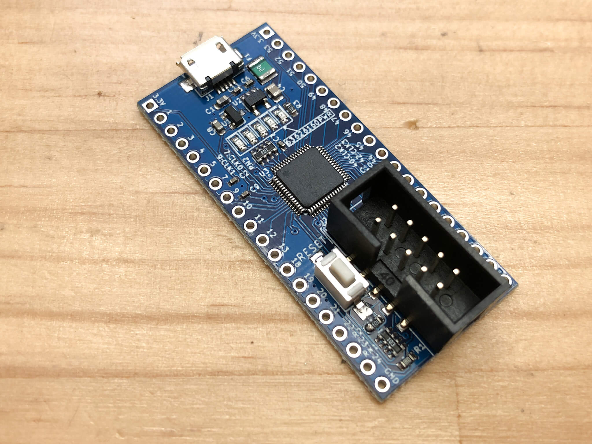
In this case, I would like to make a long and thin board for experiments that can be inserted into a breadboard while outputting as many CPLD pins as possible to the pin headers.
Design with KiCad
Schematic

I used the previous circuit and it's pretty much the same. The power supply regulator has been changed to a small capacity and smaller type.
Of the output pins of CPLD, 1 to 24 pins and 36 pins (34 to 53) are pulled out to the pin header. In addition, 4 pins (60 to 63) are connected to the LED so that it can be used for testing.
Artwork

This time, I tried to wire it with an auto router. It looks like it's wired pretty well.
The booklet that comes with this "Transistor Technology" is very useful as a manual on how to use KiCad.

3D View
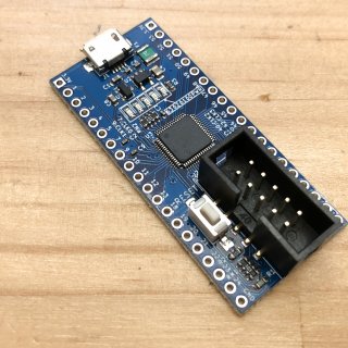
The JTAG connector at the bottom of the substrate is quite large and occupies the entire width of the substrate. If the placement was vertical, we might have been able to make a narrower substrate.
Imposition

In a typical Chinese substrate manufacturer, the price does not change up to a size of 10cm x 10cm. Also, in order to have a V-cut trench dug on the substrate, the substrate size must be at least 7cm x 7cm. The size of this one board is 3 cm x 5 cm, so by placing three of them, I made sure that it was more than 7 cm but less than 10 cm.
Alignment holes
Holes are drilled in the corners around the substrate to align with the stencil. A 1mm diameter hole is drilled in the substrate and a 1mm diameter pad is placed in the same position. This way, the holes will be in the same position on both the board and the stencil. By sticking a thumbtack into this hole, you can easily align the stencil with the board.

However, when ordering stencils, you need to set the "Fiducials" setting to "Etched Through". By default, it is set to "No Fiducial".
Even if there is a hole in the stencil data-wise, if the setting is "No Fiducial", the operator of the substrate shop may ignore this hole and there will be no hole in the stencil. Make sure you set it to "Etched Through".
Design Complete

Now, the substrate design is complete. All that's left to do is place an order. I'd like to order the other substrates together, so I'd like to order them after they are completed.
2020.5.15 Additions

To allow for the use of two pins on each side of the breadboard, I redesigned the board to be narrower than the original board and then placed an order with the JLCPCB. I'm looking forward to receiving it.
Added on May 21, 2020 Click here to continue.
End of addition
you can buy here👇👇👇


コメント