

Series of designing substrates to control e-paper with the ESP32-WROVER-B, Previously, I mounted the components. This time, we are going to test the operation.
Write program to CPLD
First, write the program to the MAX V CPLD. This CPLD performs a protocol conversion that allows the ESP32 to control the electronic paper and send display data over SPI.

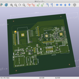
The pin assignment is different from the board I was experimenting with before, so I changed the layout with PinPlanner.

In order to download the program, the JTAG probe is placed in contact with the JTAG pad on the PCB.

When I clicked the "AutoDetect" button, it said 5M160ZE64 and the CPLD was successfully recognized. Then click on the "Start" button to write the program. The green status bar in the upper right corner of the window has been stretched to 100%. I was able to write the program successfully.
Write program to ESP32

I'm going to transfer the test program from the Arduino IDE.
Since the cheap CH340 is used for the USB serial conversion IC, the maximum transfer speed is 460800bps, but I was able to write the program normally.
PCB bug fix
Boot mode setting error

Somehow the boot mode was 0x17. The schematic shows that IO4 was not a pull down, but a pull up. It worked as it was, but I modified the PCB and changed it to pull down.

I modified the PCB and it now boots on 0x13.
Serial 2 is not available
There are three hardware serials in the ESP32, from 0 to 2. Of these, 0 is used to write the program and 1 is used inside the ESP32 and is not available to the user. I was going to use the remaining 2 (IO16,17) for communication with the GPS receiver, but for some reason I can't communicate with it. It wasn't even available as a GPIO.

Looking at the ESP32-WROVER datasheet, IO16 and IO17 of serial 2 were set to NC (not connected). Apparently, Serial 2 is used connected to the PS-RAM inside the ESP32 and is not available to the user.

I have no choice, so I'll use the IO25,26 software serial for the GPS.
Power GOOD's LED doesn't light up
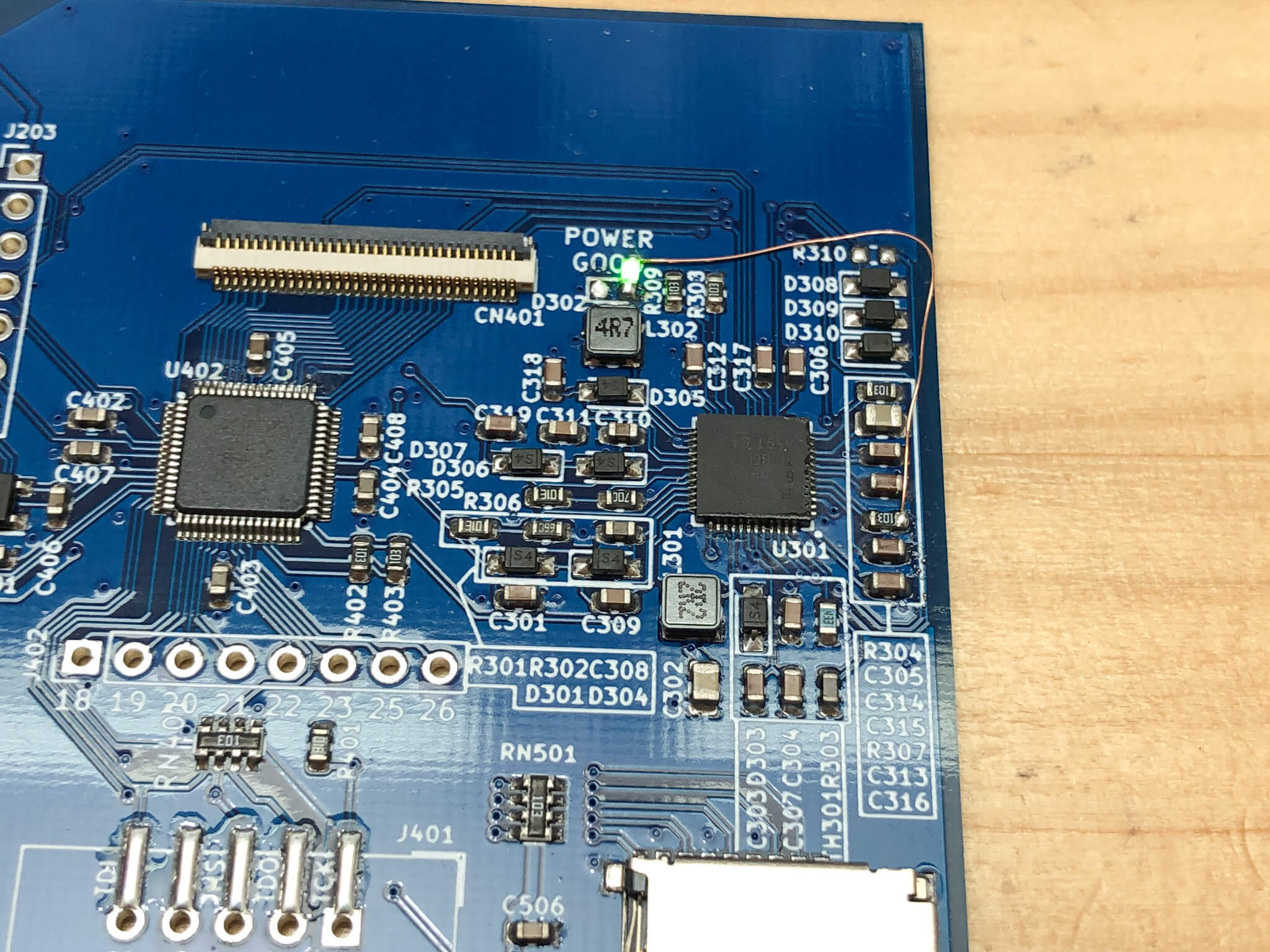
The function of this DCCD converter IC for e-paper is to output a POWER GOOD signal to indicate when the DCDC converter has started to operate and when all of the respective output voltages have reached the specified voltage. This time, I had connected an LED to that signal, but it didn't light up when I turned it on.
I checked all the output voltages, but the LED didn't light up despite everything being normal, so I checked the circuit and found that the POWER GOOD signal was not the current spitting type, but the open-drain sucking type.
After reversing the polarity of the LED and changing the wiring, they started to glow normally.
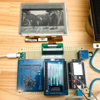
Display test by connecting electronic paper

Now that I've tested the operation of each functional unit, I can finally connect the e-paper and test to see if it can be displayed. I'd like to test the display with a program I created earlier that shows the animation.

Now the result is...
The animation was displayed and the operation test was successful ! ! !
Now that the hardware is complete, I'd like to improve the software for this experimental PCB.


コメント