The Nintendo Famicom has been remodeled into a clear video and a nice stereo output.
Translate
The Nintendo Famicom has been remodeled into a clear video and a nice stereo output.
スポンサーリンク
The sharp video output and audio stereo function of the Nintendo Famicom Video Console, which we have been experimenting with, have been modified to fit into the Famicom Mainframe.
The Famicom has only RF output, so it cannot be connected to the current TV. So let's modify it to be able to output video and audio.
Clear video output
The NES uses an RF circuit to convert the video signal from the PPU and the audio signal from the CPU into an RF signal before outputting it. Therefore, the video signal from the PPU can be intercepted and routed through a video amplifier to produce a normal video output.
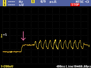
As I noticed when I saw the waveform, the video signal from the PPU of the Famicom has a slightly distorted waveform.
Like this, the part that should be sharp is dull and round. That means the image is also dull.
So I tried to compensate by filtering the curled part with the following circuit.
Let's see the difference in the video of Dragon Quest II.
スポンサーリンク
Think of 0 pf as a normal image that does nothing. The larger the number, the more distinct the outline becomes. 20 pf is just right. 44 pf is a bit overcorrected.
I named this filtered video output circuit a "Clear video output circuit".
The sound of the Famicom is monaural. However, if you look closely at the circuit, the Famicom CPU has 2 sound outputs. Pin 1 of the CPU is called AUX A, and pin 2 is called AUX B. The difference is in the sound source.
The AUX A has a 2 channel rectangular sound source connected to it, and produces the electronic sound characteristic of the Famicom.
The AUX B has 3 sound sources connected to it : "Triangle wave, noise, and ADPCM". The AUX B mainly produces bass sounds and drum sounds.
These sounds are mixed in the Famicom circuit and are output as mono. Without mixing these outputs, AUX A is the left channel and AUX B is the right channel. The left speaker produces the Famicom characteristic electronic sound, and the right speaker produces the sound of the bass and drums. This is how the sound is heard.
By assigning the sound source to the left and right channels, it looks like stereo, but I get tired when I hear a completely different sound on the left and right. So I tried to improve it to a natural stereo signal by mixing the left sound slightly to the right and the right sound slightly to the left. The circuit looks like this.
スポンサーリンク
The AUX A and AUX B signals are mixed by resistors. By connecting the resistors as shown in the figure above, you can hear each sound source at approximately 30 degrees to the left and right. Since the sound signal from the Famicom was small, it was amplified by an amplifier of 14 dB (5 times).
↓2020.2.5 Added
Including the amplifier circuit, the circuit diagram looks like this.
I set the parameters so that the number of resistors is as small as possible. In the example above, if you have only 3 types of resistors, 1k Ω, 2.2k Ω, and 10k Ω, you can assemble them. In addition, you can replace the 1k Ω resistor of resistor "R7" with 2 parallel resistors of 2.2k Ω. In this way, you can assemble them by just using 2 resistors of 2.2k Ω and 10k Ω.
If the sound is loud, try changing the resistors "R4" "and" "R10" "to lower the gain. On the other hand, if you feel the sound is low, change the resistors" R4 "" and "" R10 "" to higher values. Using a volume (electronic component) may be a good idea.
↑2020.2.5 Added.
スポンサーリンク
Make a circuits at the RF substrate size
We combined a Clear video circuit, a Nice stereo circuit, and a power supply circuit into a circuit that is the same size as the RF circuit board. The video and audio outputs were combined into a 4 pole jack of 3.5 mm, enabling the use of ordinary 3.5 mm AV cables (such as ↓).
Disconnect the cable between the original RF board and the main board.
スポンサーリンク
The original board is replaced with a new board and wiring is completed. A 10 uF ceramic capacitor is attached to the main board to protect against vertical and diagonal stripe noise. Details of the stripe protection are shown here.
The video and audio signals from the PPU and CPU are connected by a very fine shield wire, which is thin and flexible, and is very convenient for wiring in narrow areas.
スポンサーリンク
Very nice.
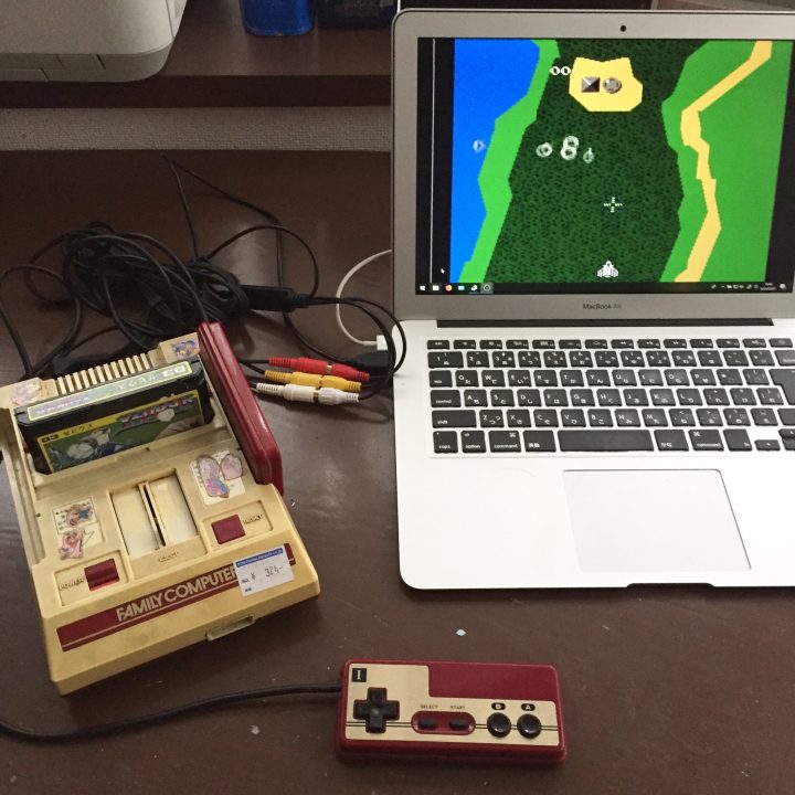
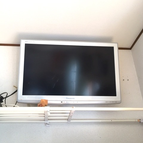
I tried playing with all the 10 or so cassettes in my house. I sold my TV to a recycle shop, I don't have a TV at home, so I play with my computer via a capture cable.
I listened to it with headphones and played it. It sounds like a stereo sound and it feels good. I don't really care about vertical stripes. It was a pretty good modification.
What I found when I tried is that the regulator generates a lot of heat, and the sound signal contains noise to match the image.
As a measure against heat generation, it is necessary to release heat firmly. The regulator of the RF board that is originally attached have a heat sink made of aluminum shield. It needs something like a heat sink.
I don't care about the sound noise at all while the music is playing, but I care about it when there is no sound. I checked where it came from, but it was originally superimposed on the sound signal from the sound output pin of the CPU, so I couldn't take any measures.
The circuit of this article has been made into a kit! We are now selling a "Modified Kit for Sharp and Crisp Picture Quality & Natural Pseudo Stereo Sound Video Output"! You can enjoy a powerful Famicom on an ordinary TV.


コメント