


I had previously designed an alarm clock type Nixie tube clock substrate and ordered a PCB from FusionPCB.

How many days does it take to receive the PCB?

I ordered that PCB on July 3 and manufacturing was completed on July 8. I also ordered another PCB along with it and that PCB was finished manufacturing on July 10. It took us roughly a week to finish manufacturing.

The package was handed over to the courier on July 13 and was in hand two days later on July 15. It only took me 2 days to get to Japan from China. That's fast.
It took about two weeks in total from ordering to receiving.
The PCBs and stencils that arrived

Here's the PCB and stencil that arrived. Matt black is beautiful.

The black is darker and cooler than the matte black of JLC PCB.

Silk printing is also very beautiful. The corners are sharp. The triangular mark on pin 1 of U2 and the square of the outer diameter are also sharp. it's very beautiful. I have been ordering boards from various board shops so far, but I feel that Fusion PCB has the highest accuracy and the quality of the finish.
Component mounting
Let's mount the parts.
Printing solder paste

First, solder paste is printed to mount the components. Place unnecessary boards around the target PCB to prevent the target PCB from moving.

Place the stencil and insert the thumbtacks to position it. By using a thumbtack, the board and stencil can be aligned and fixed without shifting.

Put solder paste on the back of the stencil.

CHIPQUIK TS391AX50, a low-melting-point lead-free solder paste, is used. The particles are fine, and they are easily separated from the stencil, so you can print neatly.

I will print the solder paste using plastic cards such as unnecessary credit cards.

The stencil accuracy is also perfect. The solder paste was printed very nicely.
Mounting surface mount components

I mount the parts with an electric vacuum pick HAKKO 394 instead of tweezers.

The tweezers have to be opened to release the tips of the tweezers. Therefore, a certain amount of space is required between parts, and it is impossible to place parts in close proximity. In the case of the electric vacuum pick, the upper surface of the parts is adsorbed with air, so there is no problem even if the space between parts is narrow. It will stick when you press the button, and the parts will separate when you release it, so you can mount it very easily without the need for concentration as compared to tweezers.
Also, if you use a feeder for surface mount parts, you can always pick up parts in a fixed orientation.

Therefore, the mounting of oriented components such as diodes and transistors is greatly facilitated. I can never go back to using tweezers anymore.

Thanks to the electric vacuum pick, the mounting of parts is progressing rapidly.

This time, I have a small number of parts, so I ended up immediately. The step-up DCDC converter (back left) board for Nixie tubes was also directly mounted.
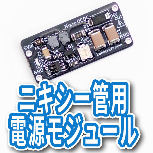
Since the terminals of the step-up DCDC converter for Nixie tubes are through-holes on the end faces, it is possible to mount them directly on the board like this.
Reflow

Reflow in a convection oven that can evenly heat the temperature inside the chamber with warm air. I use TESCOM convection oven TSF601.

Attach a thermocouple thermometer to the PCB to be reflowed and monitor the temperature.

At about 2 minutes at 100 degrees, 2 minutes at 140 degrees, and 1 minute at 160 degrees, you'll have a nice temperature profile for a low-melting solder paste. This time it was a matte black PCB, so it felt like the temperature rose sharply. The black PCB will absorb heat easily.

I was able to reflow it nicely.
Soldering DIP components

Solder a female pin header and ESP32-DevKitC.

All components are now mounted.
A nixie tube will be placed on this side. The PCB is black, but since the solder is silver and stands out a little, I paint with a matte black spray.

I masked the pin header and sprayed. Everything is matte black and looks tight.

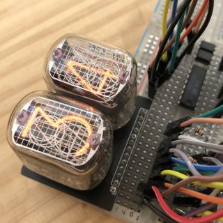
The board is completed by connecting the Nixie tube board. Last time it was the IN-14, but this time I went with the slightly smaller IN-16.
Operation check
The program of the alarm clock style Nixie tube clock that I made earlier is modified a little for this circuit.

All the features still don't work, but for now, the Nixie tube glowed normally.

The Nixie tube is beautiful, isn't it? It is beautiful and can be seen all the time.
2020.8.2 added Click here for more

End of addition


コメント